Tuesday, 13 April 2010

Wheels and Chassis Material

I have sourced the wheels and chassis material as dipicted below.


The wheels are castor wheels which are free to rotate about the virtical axis. These wheels will help support the buggy. They are assembled as shown below.


All designs will incorporate these components.

Monday, 12 April 2010

System principle

The following images illustrate the general connection system used by most line following robots:


The sensor board will be set up using the following template design:


As in our design we have opted to use 3 LEDs along with their paired LDR. The middle is mainly used as a reference to ensure the buggy does not lose track of the line.

An alternative is the use of a 2 LED and sensor system:


In this case the program is used to follow the line by tracking which sensor reads a decrease in light intensity and then moving the motors accordingly to avoid going off course. This scenario is achievable for the line-following section of the program however will have issues with the symbol reading section.

I had therefore opted and discussed with the team that it would be best to retain the middle sensor and LED to use as a guide in the line-following section and initially for the symbol reading.


Scope of Program

During the period that the program is running, 3 LED’s will remain turned on and analogue readings will be taken and processed from the LDRs.

Depending on the surface the LEDs are placed over i.e. dark strip or light floor, the amount of light reflected from the ground and picked up by the LDRs will vary.
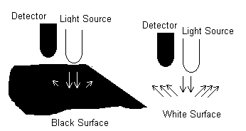


The image shows light reflection trends depending on which surface the LED has been positioned over.
If the dark strip is underneath the sensor and little/no light from the LED is reflected back to the paired LDR while if the LED shines light above the white floor then more light will be reflected back to the sensor causing the LDR to produce different analogue readings.

This is beneficial to the PicAxe controller and the program as these will cause analogue variations (using 3 ADC) that can be measured and execute the program in a particular format.

The majority of the program is designed to use the dark strip area as a reference guide for the buggy’s location.
If certain conditions are met (i.e. side sensor finds itself above a dark strip/curve) then the buggy turns right or left by changing the direction of the motor, otherwise it maintains its forward course. The other section of the program focuses on the middle sensor following the line and depending on the conditions at the end of the symbol (on each mat) it carries out a specific function.


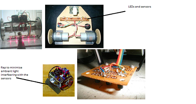
The following is an image of a typical buggy design:


http://www.fastcharged.org/robotics/firstrobot
http://www.micahcarrick.com/files/failurebot5/complete.jpg
http://www.robotgames.net/robotgames/Event_Rules/2002_line_follower.htm
http://www.ermicro.com/blog
http://www.esskayinstitute.com/LFROBOBLK.jpg
http://www.robotroom.com/NumberTwo9.html
http://www.leang.com/robotics/info/articles/linesen/pcb1.jpg

design Ideas

Line follower concept

Design “shell” ideas:

Layers


Putting several sheets of e.g. acrylic stacked on top of each other provides the opportunity to have a smaller buggy, to hopefully reduce weight and not allow the machine to be large enough to lose course once approaching a sharp bend on the path.

Wheels


A three wheeled system allows for better control of the buggy, where two (positioned either at the front or the rear) are each connected to a motor and the final smaller wheel is allowed to pivot based on the behaviour of the larger steering wheels.


Sensor Board location

The sensor board will be located close proximity to the ground and covered. This is required to avoid analogue readings (from the LDR) being influenced by a combination of LED and unwanted ambient light input.


Note: the sensor should be positioned between 1/16" to 1/8" above the ground

LED light housing


• Tubular to cover each sensor and LED (plastic)
• Block (e.g. Lego) to cover the LDR and its paired LED

Sensor

LDR sensor has been selected as the most appropriate sensor; alternatives included photo transistors, magnetic sensors...
However when tested the strip was found not to have produced a high enough field intensity to obtain the required analogue readings that would be used to control motor behaviour, therefore magnetic sensors were not used.

http://www.fastcharged.org/robotics/firstrobot
http://www.micahcarrick.com/files/failurebot5/complete.jpg
http://www.robotgames.net/robotgames/Event_Rules/2002_line_follower.htm
http://www.ermicro.com/blog
http://www.esskayinstitute.com/LFROBOBLK.jpg
http://www.robotroom.com/NumberTwo9.html
http://www.leang.com/robotics/info/articles/linesen/pcb1.jpg

Saturday, 10 April 2010

Initial Buggy Design

This is my initial design for the buggy chassis, without the circuit or drive wheels attached. The circuit would be mounted in between the top and base, and the drive wheels would be mounted in the location highlighted on the engineering drawing.

Firstly, here are CAD images of the buggy from two angles.


And here is a CAD engineering drawing of this initial design from multiple angles

LED mounting

The LED's must be mounted at the front of the buggy, close to the LDR sensors. The following images show the type of arrangement needed for the sensor board to be effective.


http://www.micahcarrick.com/05-27-2006/failurebot-line-following-robot.html

This design would work well under normal conditions, however since the LED and sensor array is not well shielded, the buggy may loss its ability to distinguish between light and dark regions in more extreme ambient light situations.

The solution to this is to introduce shielding to direct the light from the LED's towards a small spot on the ground. The following example shows this principle at work.


http://www.wa4dsy.net/robot/polyathlon-robot/polymax-improvements

This will significantly increase the efficiency of the buggy and the range of ambient light conditions in which it can operate. Below is a rough CAD image of the LED encased in a drinking straw to help direct light to a small area of ground underneath the buggy.


The LDR's will also have to be shielded in a similar fashion.

Project Update (10/04/2010)

Project Progress
The project has slipped behind slightly over the Easter holidays, however it is not yet time to start considering an action plan. The Gantt chart below shows the buggy progress to be one day behind.


The components have all been sourced and so the final tasks required include circuit and buggy assembly. The design of the buggy will be finalised during this construct phase.

Assignments

Mark Hawkins: Direct Assembly of Circuit and Buggy

Sophie Latham: Oversee Buggy Assembly and Assist Construction as Required

Sandra Donohoe: Test Program on Buggy and Assist Construction as Required

Anand Bhana: Solder Circuit and Test

Daljinder Sandhu: Finalise Design and Construct Buggy

All Members: Continue Posting and Begin Work on Personal Page Sections of the Blog

Friday, 9 April 2010

Initial Design Research

The first stage of research was to look at some other robot designs on the Internet. The first was a line following buggy whose chassis was made from a sandwich box. This robot is shown and referenced below.


www.arrickrobotics.com/robomenu/sandwich.html

This robot seemed simple and easy to make. The advantages of a robot such as this would be that the box could be opened easily for maintenance, and that it could be easily decorated. The box I decided to consider if we were to choose a design such as this was an ice-cream tub of the approximate type shown below.


With farther thought however, this design did not seem challenging enough and so I continued researching robot designs. The next potential design considered was a stacked layer robot such as the two below.


www.robotroom.com/Repairs.html

I did consider using a construction toy such as Lego or Meccano, though this seemed too simple for the purposes of this project. The most impressive design I found was of a robot made from multiple plastic components bolted together. The particular robot shown below is the Microbric Viper, though we would of course design our own.


www.microbric.com/page.php?sId=19

The design I will be focusing on will be made from multiple plastic sections. The sections will be cut to fit and stacked, with the circuits and other components sandwiched in layers. I believe this will create the most impressive robot, though it may be impractically complex to build. This design will have two caster wheels, one at the front and one at the back, and will have its drive wheels on the sides in the middle of the robot. Concept drawings of this design will be posted here soon.