I found this project to be very enjoyable and interesting. I have learned a lot with respect to working in a team and building and designing a buggy.
Towards the end there were a few issues with the programming and design. This was due to the late completion of the design and lack of work done during the easter break.
As a whole I feel I could have contributed to the programming side. The programming was a weakness of mine which is why I had such a lack of involvement in that area. By being involved I could have improved my knowledge of programming and gained a lot more from this project.
Overall this project was still rewarding in many ways. The team worked well together and there were no major issues between team members. Seeing our buggy being successful on the test was very satisfying.
Friday, 30 April 2010
Top layer ideas
After it was decided the buggy would be made into two layers, the top layer was to be designed differently to the bottom.
Here were a few design sketches for the top layer:

Here were a few design sketches for the top layer:

Line Buggy Testing
The following shows the final tests on the buggy when it carries out line following:
Review
I would conclude that this module has been well informative and very practical. It allowed the group to turn an idea designed and formulated on paper and build an intelligent robot that can perform several important tasks specified by the brief.
One of the best aspects was that we managed to source the materials we needed from recycled or unwanted components, which was the original intention of producing as buggy that was as 'environmentally friendly' as possible.
It was found that the buggy showed good tracking skills as during the line following stages it managed to reach the half way point however unfortunately due to selected pauses and the curvature of the chassis it unfortunately had a natural tendency to turn towards the right. This coupled with the rear wheel caused the buggy to loose track of the magnetic tape at various points across the line.
The gap in the following picture between the motors (when it was attempted to show alignment using a ruler) shows they could not be perfectly aligned, this turning effect would be magnified by the fact that the wheels had a natural incline.

The rear wheel would need to be substituted with a more appropriate jockey wheel as during the line following it was noticed that it could easily catch itself on the slightly thicker than expected track (this problem was also noted in other buggies):

This property amplifies the turning effect and often made it difficult for the buggy to reverse as it would get itself easily jammed:

It was however an improvement on the initial rear wheel shown in the picture as agreed by the group it impeded movement due to its weight and required more power from the to obtain the desired turn.
An improvement on the program could include the use of a RAMP function on the output in order to gently increase torque in order to slowly accelerate and decelerate the buggy particularly as it approaches a corner. This will also reduce the chances of overshooting or provoking the oscillating/'hunting' behaviour that was noticed as soon as it lost the track.
Project Complete - PM's Review
The project is now completed with the final test concluded, as depicted by the Gantt chart below.

The project started off very well, and in the initial phases we accelerated beyond schedule. Unfortunately this progress was lost over the Easter holiday's, though we pulled the project back and completed it on time. In retrospect I should have accounted more for the inevitable decrease in group members output over the holidays and planned around them, though by motivating my team immediately as term resumed we were able to finish on time to a high standard.
The intended budget for this project was £0.00 which we were able to meet. All components were sourced for free as either unneeded spares or from recycling centres over the Easter holiday's.
The program worked well and much of the design was also good, though we were let down by the rear caster wheel. The original was sourced by me from Swindon Recycling Centre, and when tested it turned out to be to heavy and stiff. I made attempts to modify the wheel and also treated it with WD40 to loosen it, though the weight ultimately let it down. The wheel was replaced last minute with a homemade caster wheel which did not perform well on the line following mode as it would cause the buggy to veer off course whenever it tried to turn. If I were to do this project again, I would have sourced a light-weight pololu ball caster to replace this wheel.
The symbol reading part of the final test went smoothly, as the rear wheel did not have a chance to cause problems. The design assessment was acceptable, though the aesthetics of the design could have been improved with practise. Some of my cuts were not perfectly straight and the holes drilled by Anand caused the acrylic plates to crack in several places. This caused the final build to look a little rushed, and were a result of our limited experience using tools.
The power of the motors was also a little low. The battery pack was only just powerful enough to power the circuit and motors. As seen in other groups, if I were to repeat this project I would have designed a secondary power supply specifically for the motors.
In conclusion I feel this project went well. We scored highly in the final assessment and worked well as a team. To improve our project if I were to do it again I would have planned our schedule better around the Easter holiday's so that we could have had more time testing, installed a secondary power source for the motors, dedicated more time to ensuring the build was neat, and sourced a better rear caster wheel.
Final Build
I sourced the acrylic for the final build from a scrap bin at the university; and with the assistance of the Assistant PM, Electronics Specialist, and Chief Designer; began the build process.
The first stage was to measure the components, create a design, and to cut the acrylic to size. Sophie and I did the first stage of this, and then Sophie created the robot design shown below. I was then able to cut the boards to size.

Picture Taken By Sophie Latham
Sophie then, with advice from the team, used the component sizes to mark out where all holes that required drilling should be positioned and the boards were given to Anand, in the condition shown in the picture below, for him to drill at home.

Picture Taken By Sophie Latham
The next stage was for me to cut out the slots for the robots arms and legs from the top piece, whilst Anand wired in the circuit to the lower piece of acrylic. Once this was complete, Daljinder sanded down the acrylic components and I designed a variable spacer to be placed between the sensor array circuit and the lower sheet of acrylic. This design is depicted below and as the bolts shown are tightened/loosened, the array is raise/lowered respectively. This design keeps the circuit under enough tension to keep it in place without risking damage. There was concern raised about the heat from the circuit melting the sponge, though these were quickly dismissed considering the low voltage and frequency at which the circuits operated.

Picture Taken By Sophie Latham and Edited By Mark Hawkins
The result of these processes is shown below.

Picture Taken By Sophie Latham
Sophie then, with some advice from me, finished her design by using my electrical tape, and part of a disco ball, to decorate the face plate on the top of our robot. This was then bolted down and the final assembly was complete, as depicted in the images below.

Picture Taken By Sophie Latham

Picture Taken By Anand Bhana
The caster wheel on the back of this final design turned out not to be fit for purpose. It was too heavy and caused the batteries to drain too quickly with little movement.
After much debate amongst the team, Sandra's design for a new back wheel was chosen and implemented, creating the final design shown below that was used in the final test.

Picture Taken By Sandra Donohoe
The first stage was to measure the components, create a design, and to cut the acrylic to size. Sophie and I did the first stage of this, and then Sophie created the robot design shown below. I was then able to cut the boards to size.

Picture Taken By Sophie Latham
Sophie then, with advice from the team, used the component sizes to mark out where all holes that required drilling should be positioned and the boards were given to Anand, in the condition shown in the picture below, for him to drill at home.

Picture Taken By Sophie Latham
The next stage was for me to cut out the slots for the robots arms and legs from the top piece, whilst Anand wired in the circuit to the lower piece of acrylic. Once this was complete, Daljinder sanded down the acrylic components and I designed a variable spacer to be placed between the sensor array circuit and the lower sheet of acrylic. This design is depicted below and as the bolts shown are tightened/loosened, the array is raise/lowered respectively. This design keeps the circuit under enough tension to keep it in place without risking damage. There was concern raised about the heat from the circuit melting the sponge, though these were quickly dismissed considering the low voltage and frequency at which the circuits operated.
Picture Taken By Sophie Latham and Edited By Mark Hawkins
The result of these processes is shown below.

Picture Taken By Sophie Latham
Sophie then, with some advice from me, finished her design by using my electrical tape, and part of a disco ball, to decorate the face plate on the top of our robot. This was then bolted down and the final assembly was complete, as depicted in the images below.

Picture Taken By Sophie Latham

Picture Taken By Anand Bhana
The caster wheel on the back of this final design turned out not to be fit for purpose. It was too heavy and caused the batteries to drain too quickly with little movement.
After much debate amongst the team, Sandra's design for a new back wheel was chosen and implemented, creating the final design shown below that was used in the final test.

Picture Taken By Sandra Donohoe
Pictures of the final Buggy
The following pictures show a lateral view of the buggy, in particular the location of the components underneath and on top of the first layer of acrylic:


Labels were added to make it easier to connect the wires bake to their original pins as they needed to be taken appart in order to pass them through the slot that Anand created.


Labels were added to make it easier to connect the wires bake to their original pins as they needed to be taken appart in order to pass them through the slot that Anand created.


Thursday, 29 April 2010
Project Review
Reviewing the project as a completed whole, there are various tasks i believe we did well and many we could improve on.
Overall i see the project as a success, we completed the final assessment with good marks. I believe the biggest issue would have to be our time planning, in retrospect, i would have liked to have had more time building and testing. Although even when saying i believe i had more time, there was a three week period in the middle of this project where various group members, including myself, were needed elsewehere for the holidays. With this mind, although it's regretful that the three weeks were minimal work wise, i believe we did very well to complete the tasks ahead of us and create a buggy that worked and looked good.
Something i think we did well was the finance side of the buggy, we did not pay for one component, all parts were sourced second hand from garages and the tip over the three weeks holiday.
I personally believe i could have improved on my role as Assistant Project Manager (Build Team) by officially recording the group happenings more effectively. Throughout this project i have kept my group discussions and progress recorded in note form, this includes all my random ideas and personal drawings/layouts. If i had officially written these random notes and 'sketches' up, i maybe could have kept them more organised and possibly shared them more effectively with the group.
I would like to believe that i have learned much from this project but the main things would have to be how to keep the myself organised and motivated.
Posted by Sophie Latham
Final Assesment

This photo shows the buggy fully assembled during the final assesment of this project.
Posted by Sophie Latham
Buggy Testing
This video is demonstrating the initial testing of the buggy whilst line following.
The above video shows the buggy being tested at the symbol following capabillity.
Posted by Sophie Latham
Final Build

The components were collected and we began assembly.


Whilst the assembly was being completed (as shown above), i finished the robot top-plate using electrical tape and a coloured disk taking from an old disco ball. This is also shown above.

The above is the finished buggy assembly.
Posted by sophie Latham
Templates ('Robot-Robot' Idea)
After materials are gathered and the buggy design was near finish, me, Dali and Mark discussed what shape to cut the acrylic top plate into. We discussed ideas and i suggested a robot profile with stick-on features, it is a simple idea and be easily designed and cut into acrylic without taking too much time or effort. This allows us to spend more time on the build and assembly of the actual buggy frame.

The above is a picture of the paper templates i made that will allows us to cut out the overall shape of both the bottom and top acrylic plates.

We cut out the overall shape as shown above.

The above is a drawing i have done to show me hole placements, including the stripboard offset.

This is picture of the acrylic sheets with the holes marked out. They are to be completed by Anand, who will take them home and drill all the holes indicated.
Posted by Sophie Latham
Initial Design
Below is a drawing of my intial idea and an included parts list. The sketch does not include the circuits or battery pack, just the motors and frame positioning.

Posted by Sophie Latham

Posted by Sophie Latham
Back-Up Wheel Ideas
The main requirement needed of the third wheel is the need for it to move in multiple directions when the buggy turns (Ref Meeting 4). It needs to move easily with minimum drag on the motors moving the buggy. The biggest problem involved with this situation is the small size with which the wheel will be placed. Me, Mark and Anand got together and came up with three ideas.
We decided to go ahead with the idea involving a castor wheel that pivots 360 degrees and can be bolted to the buggy frame. Whilst conducting a search for a suitable wheel we found there to be a very restricted market for small castor wheels. To counter this problem we kept the 2 other original ideas as back-up, they are shown on the below sketch.

Posted by sophie Latham
Buggy Review
Now the project is over it is now time to reflect on how well the buggy preformed and how well it was designed.
As my job role was the Electronics Specialist in hindsight I would have laid out the strip board design before soldiering therefore it would have been neater and thus easier to connect the circuit to the PICACE board and the Motor board. Also looking at some other groups I saw that they were using separate power sources for the boards and the motors thus spreading the power evenly to both components as from rigorous testing of our buggy the batteries started to drain.
On the buggy design we should have sourced a better swivel wheel for our buggy as the one sourced by Mark did not turn smoothly and was slightly too heavy for the motors to pull.
One last thing I would have done better is the build of the chassis as I was drilling and cutting the holes I should have taken more care in protecting the plastic also using a centre punch to stop the drill from slipping and scratching the plastic thus keeping out buggy looking much more professional.
Overall I think that we should have built the chassis sooner which would have allowed us to test the program for longer therefore ironing out any problems it faced following the line.
Sourced material
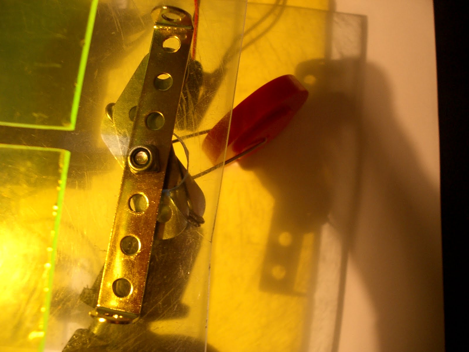
I managed to make the following jockey wheel to substitute the one that that the group had chosen to discard.
A paper clip, a provided wheel and some rejected mechano components were combined in the following format in order to create the following wheel mechanism:
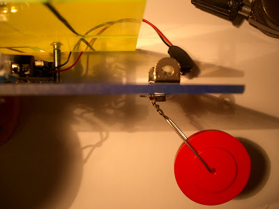


A paper clip, a provided wheel and some rejected mechano components were combined in the following format in order to create the following wheel mechanism:


Suggested ideas for design
I suggested that instead of positioning the bolts needed to support the top sheet near the robots face beside the coloured caps for eyes (suggested by Daljinder) which could potentially distort Sophie's robot design, to instead masquerade them into becoming part of the final design as pupils for the robots eyes.

Sophie annotated the final design and obtained the following:


Sophie annotated the final design and obtained the following:

Final Program
The chief programmer presented the initial final program to the group the day before the final test, though on occasion the buggy would stop when it lost the posistion of the track. As a result the project manager suggested a feed back reversing system whenever the central track relation sensor recorded a white background. This was then installed to produce the final program, which was then calibrated by the programmer.
The following is the final program:


The following is the final program:


Monday, 26 April 2010
Build Stages
Throughout the build pictures were taken to show the stages at which the build was at.
23/03/2010


25/04/2010
Final chassis desgin was finalised and I drilled holes for the motor, circuit, second layer of plastic and 2 slots for the wires from the circuit it pass through.


26/04/2010
Finial circuit build to wire up circuit to PIC board and Motor board as well as back-up wheel arragement. Mark cut the slots for the top layer and then I wired up the circuit and bolted on the motors then bolted the circuit with a foam layer inbetween to act as a spacer so that the circuit is closer to the ground.


23/03/2010


Complete test using breadboard...
19/04/2010
Circuit soldered using strip board instead of breadboard.


Me and Mark soldered the circuit, and then I made holes for the board to be secured to the chassis. I also sourced some super glue, zip ties and various types of screws and bolts.
25/04/2010
Final chassis desgin was finalised and I drilled holes for the motor, circuit, second layer of plastic and 2 slots for the wires from the circuit it pass through.


26/04/2010
Finial circuit build to wire up circuit to PIC board and Motor board as well as back-up wheel arragement. Mark cut the slots for the top layer and then I wired up the circuit and bolted on the motors then bolted the circuit with a foam layer inbetween to act as a spacer so that the circuit is closer to the ground.


Subscribe to:
Comments (Atom)