The following shows the final tests on the buggy when it carries out line following:
Showing posts with label Sandra Donohoe. Show all posts
Showing posts with label Sandra Donohoe. Show all posts
Friday, 30 April 2010
Review
I would conclude that this module has been well informative and very practical. It allowed the group to turn an idea designed and formulated on paper and build an intelligent robot that can perform several important tasks specified by the brief.
One of the best aspects was that we managed to source the materials we needed from recycled or unwanted components, which was the original intention of producing as buggy that was as 'environmentally friendly' as possible.
It was found that the buggy showed good tracking skills as during the line following stages it managed to reach the half way point however unfortunately due to selected pauses and the curvature of the chassis it unfortunately had a natural tendency to turn towards the right. This coupled with the rear wheel caused the buggy to loose track of the magnetic tape at various points across the line.
The gap in the following picture between the motors (when it was attempted to show alignment using a ruler) shows they could not be perfectly aligned, this turning effect would be magnified by the fact that the wheels had a natural incline.

The rear wheel would need to be substituted with a more appropriate jockey wheel as during the line following it was noticed that it could easily catch itself on the slightly thicker than expected track (this problem was also noted in other buggies):

This property amplifies the turning effect and often made it difficult for the buggy to reverse as it would get itself easily jammed:

It was however an improvement on the initial rear wheel shown in the picture as agreed by the group it impeded movement due to its weight and required more power from the to obtain the desired turn.
An improvement on the program could include the use of a RAMP function on the output in order to gently increase torque in order to slowly accelerate and decelerate the buggy particularly as it approaches a corner. This will also reduce the chances of overshooting or provoking the oscillating/'hunting' behaviour that was noticed as soon as it lost the track.
Pictures of the final Buggy
The following pictures show a lateral view of the buggy, in particular the location of the components underneath and on top of the first layer of acrylic:


Labels were added to make it easier to connect the wires bake to their original pins as they needed to be taken appart in order to pass them through the slot that Anand created.


Labels were added to make it easier to connect the wires bake to their original pins as they needed to be taken appart in order to pass them through the slot that Anand created.


Thursday, 29 April 2010
Sourced material
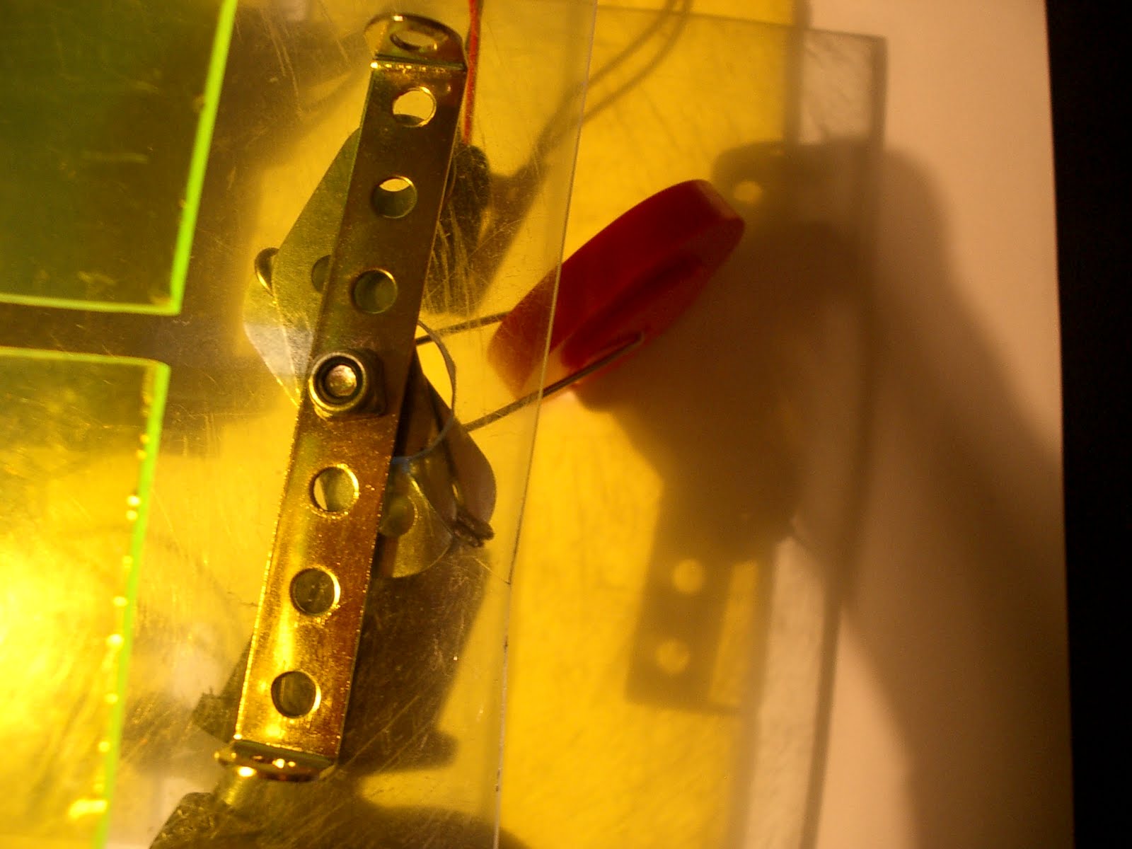
I managed to make the following jockey wheel to substitute the one that that the group had chosen to discard.
A paper clip, a provided wheel and some rejected mechano components were combined in the following format in order to create the following wheel mechanism:
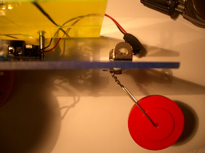


A paper clip, a provided wheel and some rejected mechano components were combined in the following format in order to create the following wheel mechanism:


Suggested ideas for design
I suggested that instead of positioning the bolts needed to support the top sheet near the robots face beside the coloured caps for eyes (suggested by Daljinder) which could potentially distort Sophie's robot design, to instead masquerade them into becoming part of the final design as pupils for the robots eyes.

Sophie annotated the final design and obtained the following:


Sophie annotated the final design and obtained the following:

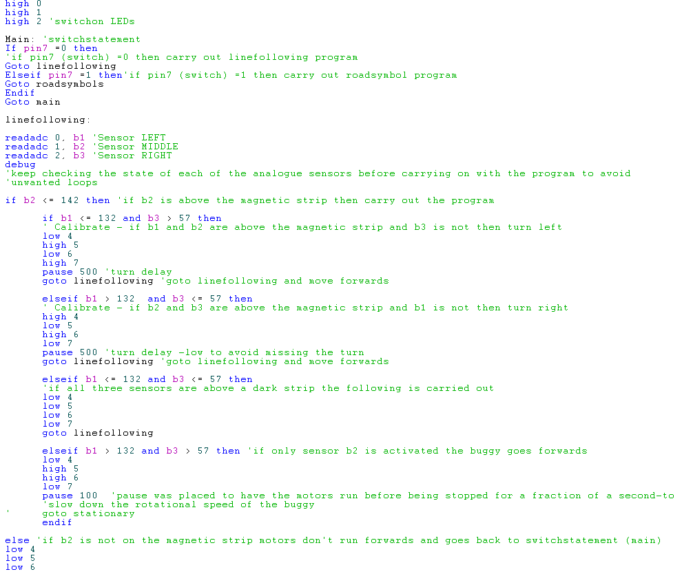
Final Program
The chief programmer presented the initial final program to the group the day before the final test, though on occasion the buggy would stop when it lost the posistion of the track. As a result the project manager suggested a feed back reversing system whenever the central track relation sensor recorded a white background. This was then installed to produce the final program, which was then calibrated by the programmer.
The following is the final program:


The following is the final program:


Monday, 26 April 2010
New code for motor directions and buggy program
Once the final assembly was carried out the final changes were made into the program:
Motor directions

Pen-ultimate program (ready to be assessed by the group and approved by the project manager)


Motor directions

Pen-ultimate program (ready to be assessed by the group and approved by the project manager)

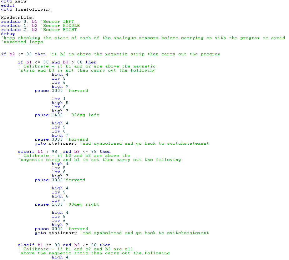

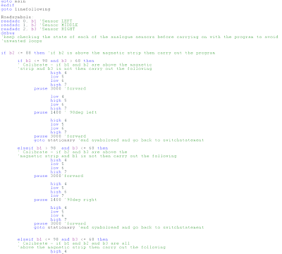
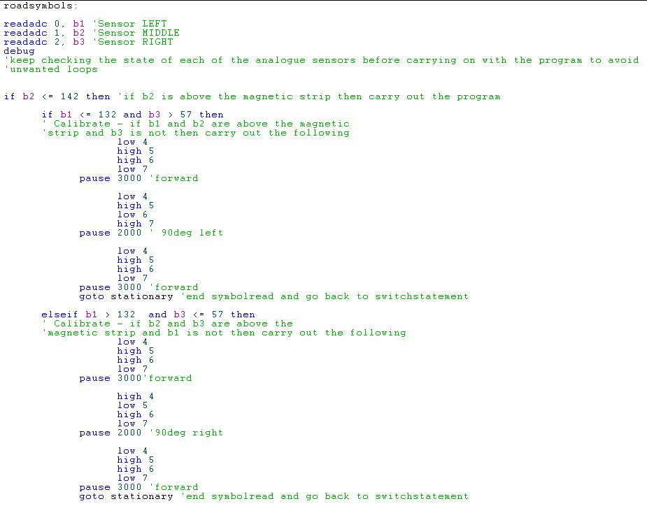
Program roadsymbols part
The roadsymbols section of the program was altered in order to allow the buggy to read specific signals and carry out a strict task depending on which sensor is activated.
It follows the same principle as the linefollowing section where the program checks accordingly innitially if the middle sensor has been placed above a dark surface and then whether any of the other conditions were met.
i.e it follows the magnetic strip then at the end of the symbol reads the final stage then depending on which sensors are also showing signs of being positioned over a dark strip will carry out 1 of three tasks. (saves memory space)

Threshold levels
The following thresholds required changing when it was tested (it will be applied to the current program)
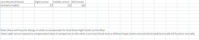
Important Note: these will require recalibration as:
- these tests are specifically designed for the prototype. To obtain the final thresholds we would need to wait until the final completed assembly as currently the circuit board is not low enough to show the likely threshold levels (and at its present height the sensors can react to shadows).
- Depending on where the buggy will be placed (floor or table) and the time of day the light intensity will vary. This will need to be accounted for and adjusted appropriately.
-time delaysd would also require calibration for turning 90 deg and linefollowing


Code for motor directions
Whilst testing the prototype other noticeable issues were found and have lead to the following changes.
The original outputs to the motor drive (to turn the wheels in a specific direction) were noticed to have caused the buggy to have turned and followed a different root to what was intended by the project brief.
This was noticed particularly when testing the symbols code (particularly the middle symbol as it was found to go forwards and turn right rather than go forwards and then reverse):

I then changed the program to take into account of the new conditions:

Sunday, 25 April 2010
tested prototype buggy
As Anand finished the holes for the acrylic layers, I made a prototype buggy to test some of the capabilities and properties the final design would have (where there could be issues and how could they be solved) as well as getting an opportunity to test the code to sort out the main issues before calibration can begin for the final model.
My findings show:
The test clearly shows that due to the light weight properties of the buggy, it is travelling at much faster speed than anticipated (a section would need changing in the program to compensate).
Another factor requiring attention was the possibility that all three sensors would find themselves on a dark line (the buggy would carry on moving in a random fashion as this situation was not accounted for in the first program).
Therefore program 1 was changed to list the the most plausible actions which the buggy could undertake should the middle sensor shows dark levels.
A double "if...then \ elseif...then \ else \ endif" statements was imposed.
The main statement was to check if the conditions showed b2 as being over a dark strip (which would lead into the next statement) else it would stop (assume under light conditions). This eliminated not only the condition should all the sensors be found over a dark strip but allowed the side sensors to be checked every cycle to reduce the chances that the buggy does not find itself under the "pause" condition while reading the b2 sensor and miss the side side sensor going bellow the threshold level as it comes across a turn.
The 4 plausible combinations when b2 is on are: all on, middle and left, middle and right and only middle sensor activated.

I designed the program as the team initially interpreted from the brief for a toggle switch (which would be sourced or an elastic band could be tied round the provided push switch to mimic the behaviour of a toggle switch).

Another factor which would need changing are the threshold light levels that the LDRs react to, the motor directions and delay timings.
Prototype movies :
Proudly sponsored by Kleenex and by Jaws the revenge
My findings show:
The test clearly shows that due to the light weight properties of the buggy, it is travelling at much faster speed than anticipated (a section would need changing in the program to compensate).
Another factor requiring attention was the possibility that all three sensors would find themselves on a dark line (the buggy would carry on moving in a random fashion as this situation was not accounted for in the first program).
Therefore program 1 was changed to list the the most plausible actions which the buggy could undertake should the middle sensor shows dark levels.
A double "if...then \ elseif...then \ else \ endif" statements was imposed.
The main statement was to check if the conditions showed b2 as being over a dark strip (which would lead into the next statement) else it would stop (assume under light conditions). This eliminated not only the condition should all the sensors be found over a dark strip but allowed the side sensors to be checked every cycle to reduce the chances that the buggy does not find itself under the "pause" condition while reading the b2 sensor and miss the side side sensor going bellow the threshold level as it comes across a turn.

The 4 plausible combinations when b2 is on are: all on, middle and left, middle and right and only middle sensor activated.

I designed the program as the team initially interpreted from the brief for a toggle switch (which would be sourced or an elastic band could be tied round the provided push switch to mimic the behaviour of a toggle switch).

Another factor which would need changing are the threshold light levels that the LDRs react to, the motor directions and delay timings.
Prototype movies :
Proudly sponsored by Kleenex and by Jaws the revenge
Sunday, 18 April 2010
Design Idea 2
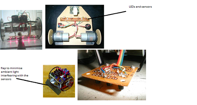
Whilst the team was discussing design ideas for the buggy casing, I suggested to use the following structure where the main circuit board, batteries, picaxe board and motor drive are placed on the top acrylic layer and only the sensors and LEDs are connected by an extended cable and held in place a short distance from the floor.
(the closer they can be to the floor along with the most lateral coverege available will avoid ambient light from affecting the behaviour of the buggy).
This feature would avoid a large number of long wire cables that will be required to connect to the top layer of the acylic to either the picaxe board or the motor drive (if wires are not positioned properly they could catch on the tyres, impeding its movement or could lead to damaged components).

This is a theme which could be used in order to make the buggy more appealing to the human eye.

Friday, 16 April 2010
Design Ideas
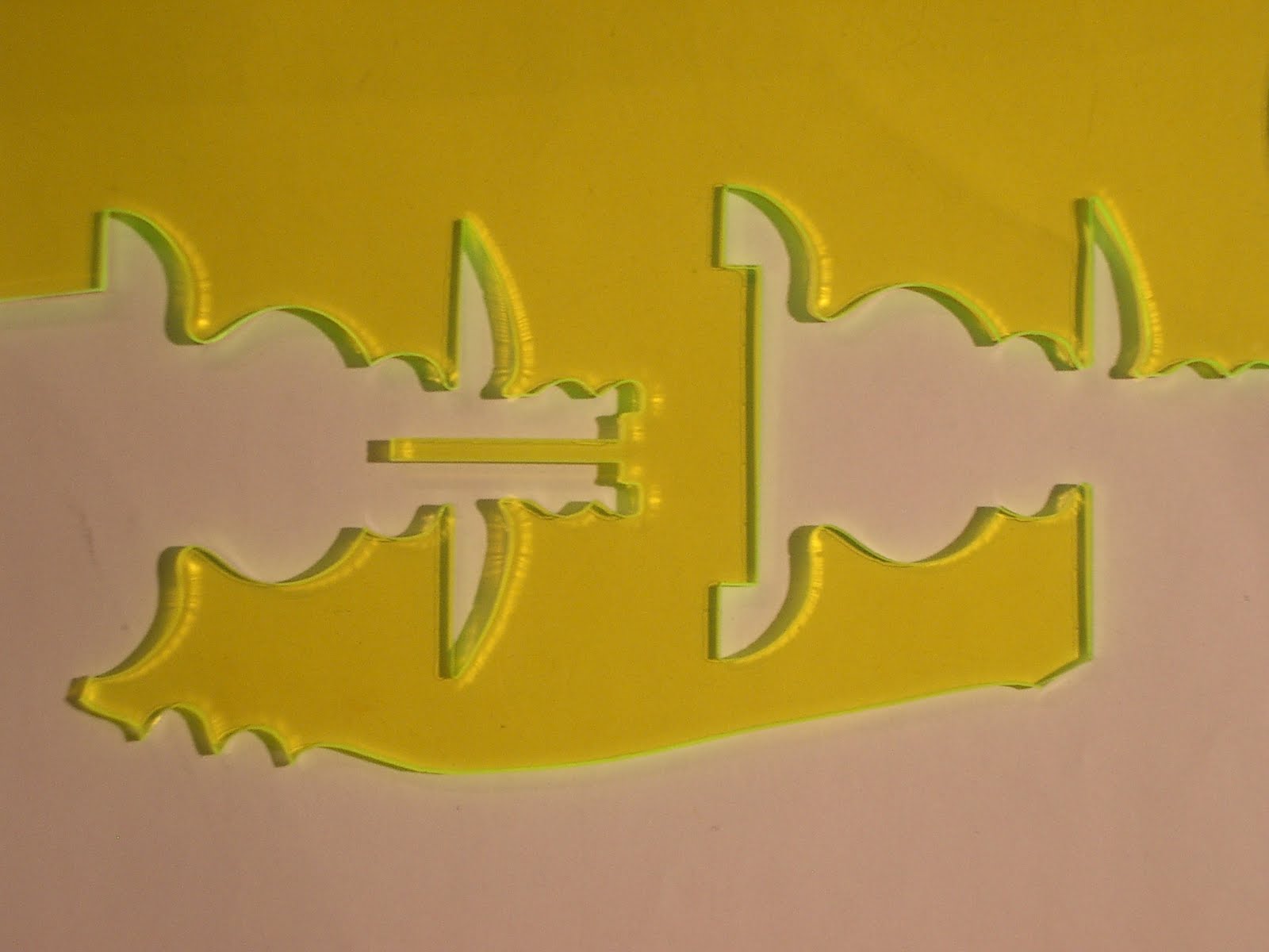
To assist the design team with the buggy layout, I suggested using the following pieces of acrylic which were sourced from a previous project (in particular with patterned shapes in order to improve overall appearance of the buggy):


Beneficial features of this type of acrylic
These pieces of acrylic have the added benefit of being fluorescent so under low light intensity the sides fluoresce adding a different finish to the final product.


Beneficial features of this type of acrylic
These pieces of acrylic have the added benefit of being fluorescent so under low light intensity the sides fluoresce adding a different finish to the final product.


Monday, 12 April 2010
System principle
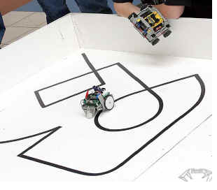
The following images illustrate the general connection system used by most line following robots:

The sensor board will be set up using the following template design:

As in our design we have opted to use 3 LEDs along with their paired LDR. The middle is mainly used as a reference to ensure the buggy does not lose track of the line.
An alternative is the use of a 2 LED and sensor system:

In this case the program is used to follow the line by tracking which sensor reads a decrease in light intensity and then moving the motors accordingly to avoid going off course. This scenario is achievable for the line-following section of the program however will have issues with the symbol reading section.
I had therefore opted and discussed with the team that it would be best to retain the middle sensor and LED to use as a guide in the line-following section and initially for the symbol reading.
Scope of Program
During the period that the program is running, 3 LED’s will remain turned on and analogue readings will be taken and processed from the LDRs.
Depending on the surface the LEDs are placed over i.e. dark strip or light floor, the amount of light reflected from the ground and picked up by the LDRs will vary.
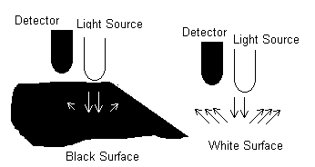
The image shows light reflection trends depending on which surface the LED has been positioned over.
If the dark strip is underneath the sensor and little/no light from the LED is reflected back to the paired LDR while if the LED shines light above the white floor then more light will be reflected back to the sensor causing the LDR to produce different analogue readings.
This is beneficial to the PicAxe controller and the program as these will cause analogue variations (using 3 ADC) that can be measured and execute the program in a particular format.
The majority of the program is designed to use the dark strip area as a reference guide for the buggy’s location.
If certain conditions are met (i.e. side sensor finds itself above a dark strip/curve) then the buggy turns right or left by changing the direction of the motor, otherwise it maintains its forward course. The other section of the program focuses on the middle sensor following the line and depending on the conditions at the end of the symbol (on each mat) it carries out a specific function.
The following is an image of a typical buggy design:

http://www.fastcharged.org/robotics/firstrobot
http://www.micahcarrick.com/files/failurebot5/complete.jpg
http://www.robotgames.net/robotgames/Event_Rules/2002_line_follower.htm
http://www.ermicro.com/blog
http://www.esskayinstitute.com/LFROBOBLK.jpg
http://www.robotroom.com/NumberTwo9.html
http://www.leang.com/robotics/info/articles/linesen/pcb1.jpg
design Ideas
Line follower concept
Design “shell” ideas:
Layers

Putting several sheets of e.g. acrylic stacked on top of each other provides the opportunity to have a smaller buggy, to hopefully reduce weight and not allow the machine to be large enough to lose course once approaching a sharp bend on the path.
Wheels

A three wheeled system allows for better control of the buggy, where two (positioned either at the front or the rear) are each connected to a motor and the final smaller wheel is allowed to pivot based on the behaviour of the larger steering wheels.
Sensor Board location
The sensor board will be located close proximity to the ground and covered. This is required to avoid analogue readings (from the LDR) being influenced by a combination of LED and unwanted ambient light input.

Note: the sensor should be positioned between 1/16" to 1/8" above the ground
LED light housing

• Tubular to cover each sensor and LED (plastic)
• Block (e.g. Lego) to cover the LDR and its paired LED
Sensor
LDR sensor has been selected as the most appropriate sensor; alternatives included photo transistors, magnetic sensors...
However when tested the strip was found not to have produced a high enough field intensity to obtain the required analogue readings that would be used to control motor behaviour, therefore magnetic sensors were not used.
http://www.fastcharged.org/robotics/firstrobot
http://www.micahcarrick.com/files/failurebot5/complete.jpg
http://www.robotgames.net/robotgames/Event_Rules/2002_line_follower.htm
http://www.ermicro.com/blog
http://www.esskayinstitute.com/LFROBOBLK.jpg
http://www.robotroom.com/NumberTwo9.html
http://www.leang.com/robotics/info/articles/linesen/pcb1.jpg

Design “shell” ideas:
Layers

Putting several sheets of e.g. acrylic stacked on top of each other provides the opportunity to have a smaller buggy, to hopefully reduce weight and not allow the machine to be large enough to lose course once approaching a sharp bend on the path.
Wheels

A three wheeled system allows for better control of the buggy, where two (positioned either at the front or the rear) are each connected to a motor and the final smaller wheel is allowed to pivot based on the behaviour of the larger steering wheels.
Sensor Board location
The sensor board will be located close proximity to the ground and covered. This is required to avoid analogue readings (from the LDR) being influenced by a combination of LED and unwanted ambient light input.
Note: the sensor should be positioned between 1/16" to 1/8" above the ground
LED light housing

• Tubular to cover each sensor and LED (plastic)
• Block (e.g. Lego) to cover the LDR and its paired LED
Sensor
LDR sensor has been selected as the most appropriate sensor; alternatives included photo transistors, magnetic sensors...
However when tested the strip was found not to have produced a high enough field intensity to obtain the required analogue readings that would be used to control motor behaviour, therefore magnetic sensors were not used.
http://www.fastcharged.org/robotics/firstrobot
http://www.micahcarrick.com/files/failurebot5/complete.jpg
http://www.robotgames.net/robotgames/Event_Rules/2002_line_follower.htm
http://www.ermicro.com/blog
http://www.esskayinstitute.com/LFROBOBLK.jpg
http://www.robotroom.com/NumberTwo9.html
http://www.leang.com/robotics/info/articles/linesen/pcb1.jpg
Subscribe to:
Posts (Atom)