Along with being assigned the role of Lead Programmer I was asked by the Project Manager to create an initial program design in order to begin testing as soon as the circuit board had been built.
The following is the experimental program which will be tested for the buggy project
_____________________________________________________________
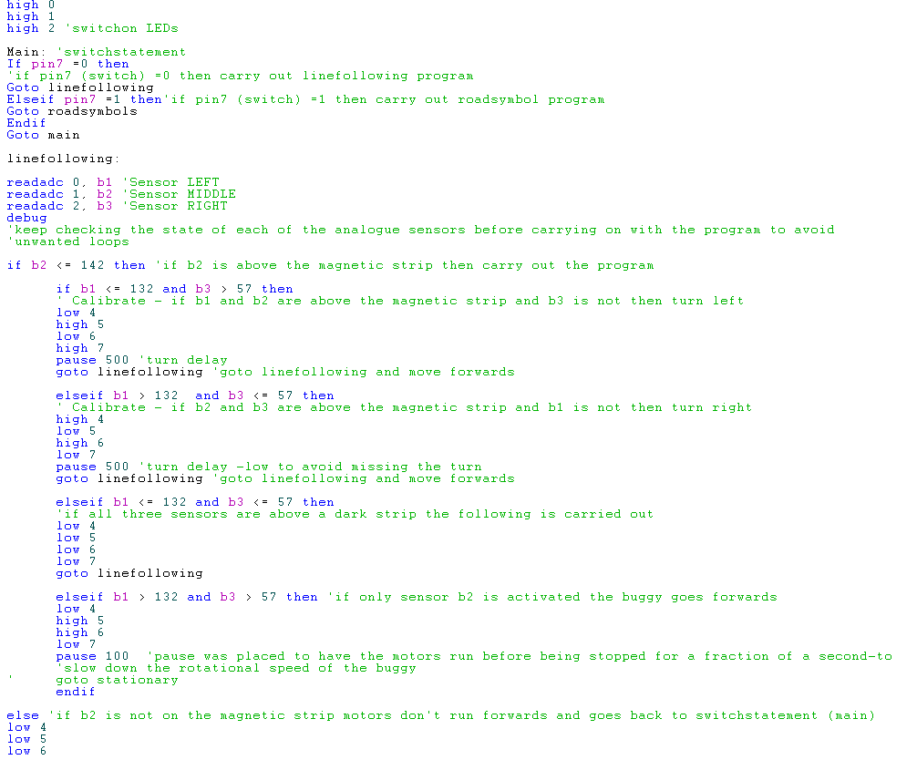
Main: 'switchstatement
If pin7 =0 then 'if pin7 (switch) =0 then carry out linefollowing program
Goto linefollowing
Else 'if pin7 (switch) =1 then carry out roadsymbol program
Goto roadsymbols
Endif
Goto main
linefollowing:
readadc 0, b1 'Sensor LEFT
readadc 1, b2 'Sensor MIDDLE
readadc 2, b3 'Sensor RIGHT
'keep checking the state of each of the analogue sensors before carrying on with the program to avoid unwanted loops
if b2 > 50 then 'if b2 is above the magnetic strip then carry out the program
high 1
low 2
high 3
low 4
'time delay?
goto sideresleft 'first check to see if left sesor has become activated
else
low 1
low 2
low 3
low 4
goto main
'if b2 is not on the magnetic strip motors don't run forwards and goes back to switchstatement (main)
endif
goto linefollowing 'repeat
sideresleft:
if b1 > 50 and b2 > 50 and b3 < 50 then
' Calibrate - if b1 and b2 are above the magnetic strip and b3 is not then turn left
high 1
low 2
low 3
high 4
pause 1000 'turn delay
goto linefollowing 'goto linefollowing and move forwards
else
goto sideresright
' if conditions are not met left sensor is not above the magnetic strip therefore move to check if the right sensor has moved above the magnetic strip before returning to the linefollowing program
endif
sideresright:
if b1 < 50 and b2 > 50 and b3 > 50 then
' Calibrate - if b2 and b3 are above the magnetic strip and b1 is not then turn right
low 1
high 2
high 3
low 4
pause 1000 'turn delay -low to avoid missing the turn
goto linefollowing 'goto linefollowing and move forwards
else
goto linefollowing
'if conditions are not met return to linefollowing program and carry on forwards
endif
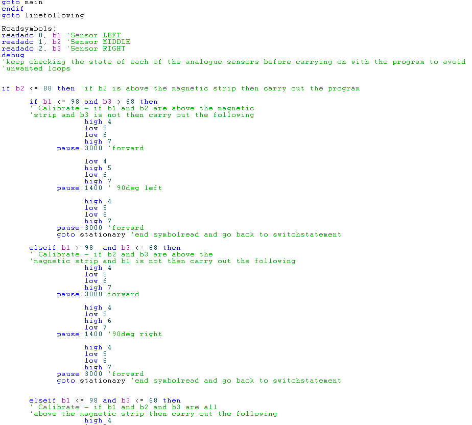
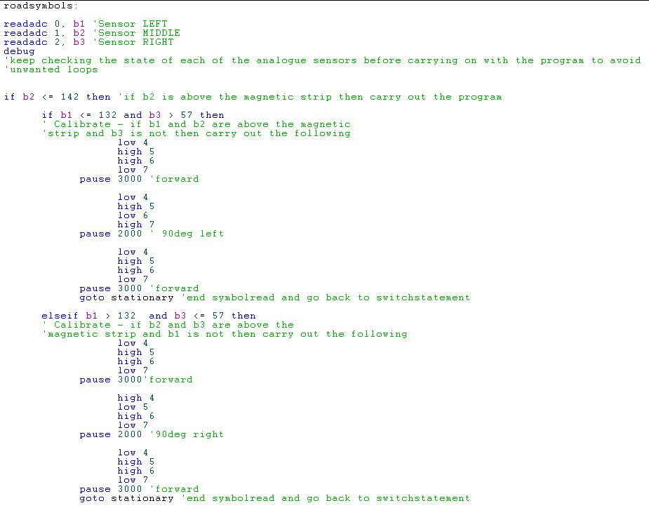
roadsymbols:
readadc 0, b1 'Sensor LEFT
readadc 1, b2 'Sensor MIDDLE
readadc 2, b3 'Sensor RIGHT
'keep checking the state of each of the analogue sensors before carrying on with the program to avoid unwanted loops
if b2 >= 50 then
' middle sensor must be placed over magnetic strip line for the program to be executed or it returns to switchstatement
high 1
low 2
high 3
low 4
pause 500 'moves forward to read symbol
if b1 >= 50 and b2 >= 50 and b3 < 50 then
' Calibrate - if b1 and b2 are above the magnetic strip and b3 is not then carry out the following
high 1
low 2
high 3
low 4
pause 1000 'forward
low 1
high 2
high 3
low 4
pause 300 ' 90deg left
high 1
low 2
high 3
low 4
pause 1000 'forward
goto stationary 'end symbolread and go back to switchstatement
elseif b1 >= 50 and b2 >= 50 and b3 >= 50 then
' Calibrate - if b1 and b2 and b3 are all above the magnetic strip then carry out the following
high 1
low 2
high 3
low 4
pause 1000 'forward
low 1
low 2
low 3
low 4
pause 1000 'stop
low 1
high 2
low 3
high 4
pause 1000 'reverse back to start
goto stationary 'end symbolread and go back to switchstatement
elseif b1 < 50 and b2 >= 50 and b3 >= 50 then
' Calibrate - if b2 and b3 are above the magnetic strip and b1 is not then carry out the following
high 1
low 2
high 3
low 4
pause 1000'forward
high 1
low 2
low 3
high 4
pause 300 '90deg right
high 1
low 2
high 3
low 4
pause 1000 'forward
goto stationary 'end symbolread and go back to switchstatement
endif
else
goto stationary
endif
goto roadsymbols
stationary:
low 1
low 2
low 3
low 4
goto main
___________________________________________________________
Posted by Sandra Donohoe