Showing posts with label Design Process. Show all posts

Friday, 30 April 2010

Top layer ideas

After it was decided the buggy would be made into two layers, the top layer was to be designed differently to the bottom.

Here were a few design sketches for the top layer:

Pictures of the final Buggy

The following pictures show a lateral view of the buggy, in particular the location of the components underneath and on top of the first layer of acrylic:


Labels were added to make it easier to connect the wires bake to their original pins as they needed to be taken appart in order to pass them through the slot that Anand created.


Thursday, 29 April 2010

Templates ('Robot-Robot' Idea)

After materials are gathered and the buggy design was near finish, me, Dali and Mark discussed what shape to cut the acrylic top plate into. We discussed ideas and i suggested a robot profile with stick-on features, it is a simple idea and be easily designed and cut into acrylic without taking too much time or effort. This allows us to spend more time on the build and assembly of the actual buggy frame.


The above is a picture of the paper templates i made that will allows us to cut out the overall shape of both the bottom and top acrylic plates.


We cut out the overall shape as shown above.


The above is a drawing i have done to show me hole placements, including the stripboard offset.


This is picture of the acrylic sheets with the holes marked out. They are to be completed by Anand, who will take them home and drill all the holes indicated.
Posted by Sophie Latham

Initial Design

Below is a drawing of my intial idea and an included parts list. The sketch does not include the circuits or battery pack, just the motors and frame positioning.


Posted by Sophie Latham

Back-Up Wheel Ideas

The main requirement needed of the third wheel is the need for it to move in multiple directions when the buggy turns (Ref Meeting 4). It needs to move easily with minimum drag on the motors moving the buggy. The biggest problem involved with this situation is the small size with which the wheel will be placed. Me, Mark and Anand got together and came up with three ideas.
We decided to go ahead with the idea involving a castor wheel that pivots 360 degrees and can be bolted to the buggy frame. Whilst conducting a search for a suitable wheel we found there to be a very restricted market for small castor wheels. To counter this problem we kept the 2 other original ideas as back-up, they are shown on the below sketch.


Posted by sophie Latham

Sourced material

I managed to make the following jockey wheel to substitute the one that that the group had chosen to discard.

A paper clip, a provided wheel and some rejected mechano components were combined in the following format in order to create the following wheel mechanism:


Suggested ideas for design

I suggested that instead of positioning the bolts needed to support the top sheet near the robots face beside the coloured caps for eyes (suggested by Daljinder) which could potentially distort Sophie's robot design, to instead masquerade them into becoming part of the final design as pupils for the robots eyes.


Sophie annotated the final design and obtained the following:

Sunday, 18 April 2010

Design Idea 2

Whilst the team was discussing design ideas for the buggy casing, I suggested to use the following structure where the main circuit board, batteries, picaxe board and motor drive are placed on the top acrylic layer and only the sensors and LEDs are connected by an extended cable and held in place a short distance from the floor.

(the closer they can be to the floor along with the most lateral coverege available will avoid ambient light from affecting the behaviour of the buggy).

This feature would avoid a large number of long wire cables that will be required to connect to the top layer of the acylic to either the picaxe board or the motor drive (if wires are not positioned properly they could catch on the tyres, impeding its movement or could lead to damaged components).


This is a theme which could be used in order to make the buggy more appealing to the human eye.

Friday, 16 April 2010

Design Ideas

To assist the design team with the buggy layout, I suggested using the following pieces of acrylic which were sourced from a previous project (in particular with patterned shapes in order to improve overall appearance of the buggy):


Beneficial features of this type of acrylic

These pieces of acrylic have the added benefit of being fluorescent so under low light intensity the sides fluoresce adding a different finish to the final product.


Wednesday, 14 April 2010

Initial Design

An initial design of the buggy:

The group decided that it was best for the design to be layered and to have the LEDs and sensor on the front at the bottom.

The two front wheels will be connected to the motors and the pivot wheel will be connected to the back of the buggy.

All of the components will be placed on the bottom layer and top layer. If possible all components may be placed on the bottom layer and the top layer will act as a cover for the components.

The hole in the bottom layer is to allow wiring from the components to the LEDs and sensors.

Tuesday, 13 April 2010

Materials

The choice of material for the buggy is very important. As there is a wide selection of materials available each with their own advantages and disadvantages, it is important to choose the right one.

It is important that the material is:
• Light
• Easy to cut
• Easy to drill holes through for mounting components
• Looks good


Wood:
Wood is light enough to be used for the buggy but it is not as light compared to some of the other materials considered. It is easy to cut and drill holes through. Also it can be painted to give the buggy a nice finish.


Metal:
Though there are many metals generally they are a lot stronger but are not as easy to cut into shape.


Plastic:
A light material which can easily be cut into a desired shape, although it is not as strong as the other materials.


Acrylic:
A clear plastic that resembles glass. It is strong, light and easy to shape. Acrylic is generally more expensive than other plastics.


References:
http://www.scioly.org/wiki/Battery_Buggy
http://www.redrc.net/wp-content/uploads/2009/12/KyoInfernoMp9e-1.jpg
http://www.wisegeek.com/what-is-acrylic.htm

Wheels and Chassis Material

I have sourced the wheels and chassis material as dipicted below.


The wheels are castor wheels which are free to rotate about the virtical axis. These wheels will help support the buggy. They are assembled as shown below.


All designs will incorporate these components.

Monday, 12 April 2010

design Ideas

Line follower concept

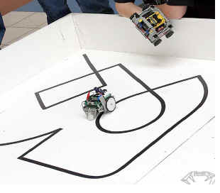
Design “shell” ideas:
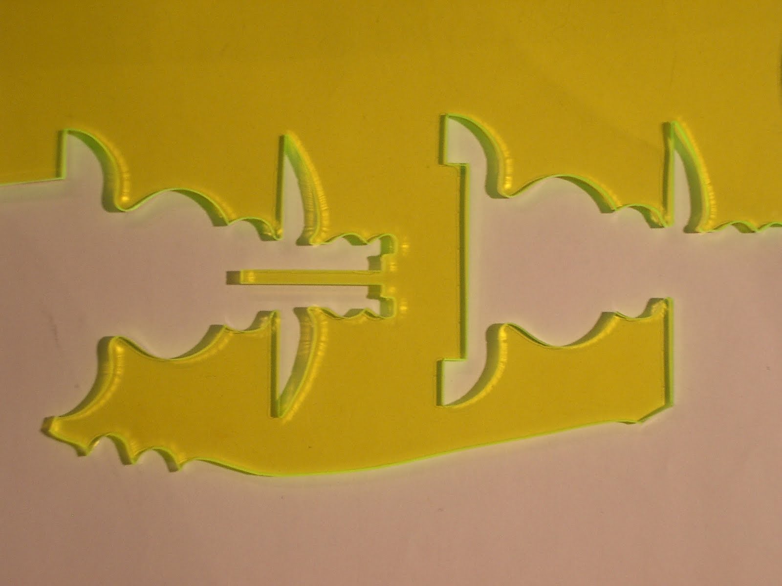
Layers


Putting several sheets of e.g. acrylic stacked on top of each other provides the opportunity to have a smaller buggy, to hopefully reduce weight and not allow the machine to be large enough to lose course once approaching a sharp bend on the path.

Wheels


A three wheeled system allows for better control of the buggy, where two (positioned either at the front or the rear) are each connected to a motor and the final smaller wheel is allowed to pivot based on the behaviour of the larger steering wheels.
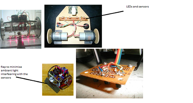


Sensor Board location

The sensor board will be located close proximity to the ground and covered. This is required to avoid analogue readings (from the LDR) being influenced by a combination of LED and unwanted ambient light input.


Note: the sensor should be positioned between 1/16" to 1/8" above the ground

LED light housing


• Tubular to cover each sensor and LED (plastic)
• Block (e.g. Lego) to cover the LDR and its paired LED

Sensor

LDR sensor has been selected as the most appropriate sensor; alternatives included photo transistors, magnetic sensors...
However when tested the strip was found not to have produced a high enough field intensity to obtain the required analogue readings that would be used to control motor behaviour, therefore magnetic sensors were not used.

http://www.fastcharged.org/robotics/firstrobot
http://www.micahcarrick.com/files/failurebot5/complete.jpg
http://www.robotgames.net/robotgames/Event_Rules/2002_line_follower.htm
http://www.ermicro.com/blog
http://www.esskayinstitute.com/LFROBOBLK.jpg
http://www.robotroom.com/NumberTwo9.html
http://www.leang.com/robotics/info/articles/linesen/pcb1.jpg

Saturday, 10 April 2010

Initial Buggy Design

This is my initial design for the buggy chassis, without the circuit or drive wheels attached. The circuit would be mounted in between the top and base, and the drive wheels would be mounted in the location highlighted on the engineering drawing.

Firstly, here are CAD images of the buggy from two angles.


And here is a CAD engineering drawing of this initial design from multiple angles

LED mounting

The LED's must be mounted at the front of the buggy, close to the LDR sensors. The following images show the type of arrangement needed for the sensor board to be effective.


http://www.micahcarrick.com/05-27-2006/failurebot-line-following-robot.html

This design would work well under normal conditions, however since the LED and sensor array is not well shielded, the buggy may loss its ability to distinguish between light and dark regions in more extreme ambient light situations.

The solution to this is to introduce shielding to direct the light from the LED's towards a small spot on the ground. The following example shows this principle at work.


http://www.wa4dsy.net/robot/polyathlon-robot/polymax-improvements

This will significantly increase the efficiency of the buggy and the range of ambient light conditions in which it can operate. Below is a rough CAD image of the LED encased in a drinking straw to help direct light to a small area of ground underneath the buggy.


The LDR's will also have to be shielded in a similar fashion.

Friday, 9 April 2010

Initial Design Research

The first stage of research was to look at some other robot designs on the Internet. The first was a line following buggy whose chassis was made from a sandwich box. This robot is shown and referenced below.


www.arrickrobotics.com/robomenu/sandwich.html

This robot seemed simple and easy to make. The advantages of a robot such as this would be that the box could be opened easily for maintenance, and that it could be easily decorated. The box I decided to consider if we were to choose a design such as this was an ice-cream tub of the approximate type shown below.


With farther thought however, this design did not seem challenging enough and so I continued researching robot designs. The next potential design considered was a stacked layer robot such as the two below.


www.robotroom.com/Repairs.html

I did consider using a construction toy such as Lego or Meccano, though this seemed too simple for the purposes of this project. The most impressive design I found was of a robot made from multiple plastic components bolted together. The particular robot shown below is the Microbric Viper, though we would of course design our own.


www.microbric.com/page.php?sId=19

The design I will be focusing on will be made from multiple plastic sections. The sections will be cut to fit and stacked, with the circuits and other components sandwiched in layers. I believe this will create the most impressive robot, though it may be impractically complex to build. This design will have two caster wheels, one at the front and one at the back, and will have its drive wheels on the sides in the middle of the robot. Concept drawings of this design will be posted here soon.