The sensor board will be set up using the following template design:

As in our design we have opted to use 3 LEDs along with their paired LDR. The middle is mainly used as a reference to ensure the buggy does not lose track of the line.
An alternative is the use of a 2 LED and sensor system:

In this case the program is used to follow the line by tracking which sensor reads a decrease in light intensity and then moving the motors accordingly to avoid going off course. This scenario is achievable for the line-following section of the program however will have issues with the symbol reading section.
I had therefore opted and discussed with the team that it would be best to retain the middle sensor and LED to use as a guide in the line-following section and initially for the symbol reading.
Scope of Program
During the period that the program is running, 3 LED’s will remain turned on and analogue readings will be taken and processed from the LDRs.
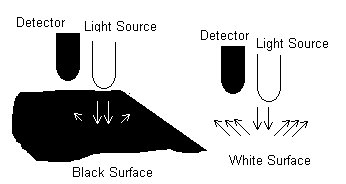
Depending on the surface the LEDs are placed over i.e. dark strip or light floor, the amount of light reflected from the ground and picked up by the LDRs will vary.

The image shows light reflection trends depending on which surface the LED has been positioned over.
If the dark strip is underneath the sensor and little/no light from the LED is reflected back to the paired LDR while if the LED shines light above the white floor then more light will be reflected back to the sensor causing the LDR to produce different analogue readings.
This is beneficial to the PicAxe controller and the program as these will cause analogue variations (using 3 ADC) that can be measured and execute the program in a particular format.
The majority of the program is designed to use the dark strip area as a reference guide for the buggy’s location.
If certain conditions are met (i.e. side sensor finds itself above a dark strip/curve) then the buggy turns right or left by changing the direction of the motor, otherwise it maintains its forward course. The other section of the program focuses on the middle sensor following the line and depending on the conditions at the end of the symbol (on each mat) it carries out a specific function.
The following is an image of a typical buggy design:

http://www.fastcharged.org/robotics/firstrobot
http://www.micahcarrick.com/files/failurebot5/complete.jpg
http://www.robotgames.net/robotgames/Event_Rules/2002_line_follower.htm
http://www.ermicro.com/blog
http://www.esskayinstitute.com/LFROBOBLK.jpg
http://www.robotroom.com/NumberTwo9.html
http://www.leang.com/robotics/info/articles/linesen/pcb1.jpg
No comments:
Post a Comment